




 Scan QR Code
Send My Request
How to Get Perfect Custom Plastic Parts According to Drawing: A Professional Guide to Injection Molding and Cost Reduction
2026-06-06
Custom parts according to drawing require precision in design and manufacturing to meet exact specifications. This Bost guide details how to achieve flawless custom plastic parts to drawing using injection molding and CNC plastic parts made to drawing while optimizing cost and production efficiency.
- 1. Core Engineering Review: From 2D/3D Drawings to Design for Manufacturability (DFM)
- 1.1 Wall Thickness Design and Uniformity
- 1.2 Rationality of the Draft Angle
- 1.3 Objective Assessment of Tolerances
- 2. Precise Material Selection: Ensuring Performance for Custom Plastic Parts
- 3. In-depth Optimization of Mold Design and Injection Molding Process
- 3.1 Precision Design of Gating and Venting Systems
- 3.2 Dynamic Thermal Balance of Mold Cooling Systems
- 3.3 Flexible Tuning of Precision Injection Parameters
- 4. Quality Control: Digital Measurement Ensures Consistency
- 5. Partner with GZ-Bost to Bring Your Drawings to Life Flawlessly
In the realm of B2B overseas sourcing and customized industrial manufacturing, transforming a design drawing into a perfect physical part is a journey fraught with technical challenges. Sourcing engineers and product managers frequently encounter severe pain points: tolerances marked on the drawing are strictly demanding, yet the actual injected samples suffer from warping, shrinkage, or dimensional deviation. How to deliver high-precision custom plastic parts according to drawing efficiently while controlling budgets is the ultimate test of an injection molding supplier's core manufacturing capabilities.
From the perspective of a veteran injection molding process and mold design expert, this article delivers a deep dive into how strict engineering reviews, material selection, and precision quality control can 100% replicate your design blueprint during the delivery of custom plastic parts.
1. Core Engineering Review: From 2D/3D Drawings to Design for Manufacturability (DFM)
Upon receiving drawings from a client, an outstanding injection molding manufacturer will never blindly open a mold. Instead, they first conduct a rigorous DFM (Design for Manufacturability) assessment. This is the decisive milestone that ensures the subsequent flawless production of custom plastic parts according to drawing.
1.1 Wall Thickness Design and Uniformity
In the injection molding process, uneven wall thickness is the primary culprit behind product shrinkage, voids, and internal stress cracking. When reviewing drawings, we pay undivided attention to whether the wall thickness transitions smoothly. If a local section is overly thick, we will recommend coring out the material without compromising structural integrity.
1.2 Rationality of the Draft Angle
If a drawing lacks an adequate draft angle, forcibly ejecting the part will cause surface scratches, ejector white marks, or even part deformation. Generally, an unpolished surface requires a draft angle of at least $0.5^\circ$ to $1^\circ$, while a textured surface demands $3^\circ$ or more.
1.3 Objective Assessment of Tolerances
Many mechanical engineers are accustomed to CNC machining tolerance standards (such as $\pm0.02\text{mm}$). However, in precision injection molding, plastics exhibit cooling shrinkage. Blindly pursuing unrealistic tolerances leads to scrapped molds and skyrocketing costs. We must clarify the tolerance zones for critical dimensions during the drawing stage based on the physical properties of the chosen plastic.
2. Precise Material Selection: Ensuring Performance for Custom Plastic Parts
To ensure the finished product perfectly matches the physical properties and application scenarios outlined in the drawing, the choice of engineering plastics is vital. Different resins exhibit distinct shrinkage rates, which directly impact the dimensional calculations in mold design.
Below is a core material comparison table we recommend for common application scenarios when handling custom plastic parts according to drawing:
| Material Type | Key Features | Shrinkage Rate Range | Typical Applications | Precision Processing Difficulty |
|---|---|---|---|---|
| ABS | High impact resistance, excellent surface gloss, great dimensional stability. | 0.4% - 0.7% | Electronic enclosures, automotive interiors, instrument panels. | Medium (Easy to control) |
| PC (Polycarbonate) | High transparency, extreme toughness, high temperature resistance. | 0.5% - 0.7% | Medical devices, optical lenses, protective shields. | Higher (Requires strict internal stress control) |
| PA66 (Nylon 66) | High mechanical strength, wear resistance, excellent self-lubrication. | 1.0% - 1.5% | Industrial gears, structural parts, automotive under-hood components. | High (Dimensions vary easily after absorbing moisture) |
| POM (Acetal) | High rigidity, low friction, superb dimensional stability (Polyoxymethylene). | 1.5% - 2.0% | Precision bearings, cams, valve components, snap-fits. | Extremely High (Requires precise shrinkage calculation) |
| PBT | Outstanding electrical insulation, chemical resistance, thermal aging resistance. | 1.5% - 2.0% | Electronic connectors, coil bobbins, automotive electrical parts. | Medium (Crystalline plastic) |
3. In-depth Optimization of Mold Design and Injection Molding Process
The mold is the mother of injection molding. To perfectly match the technical indicators of custom plastic parts according to drawing, mold manufacturing precision must reach the micron level.
3.1 Precision Design of Gating and Venting Systems
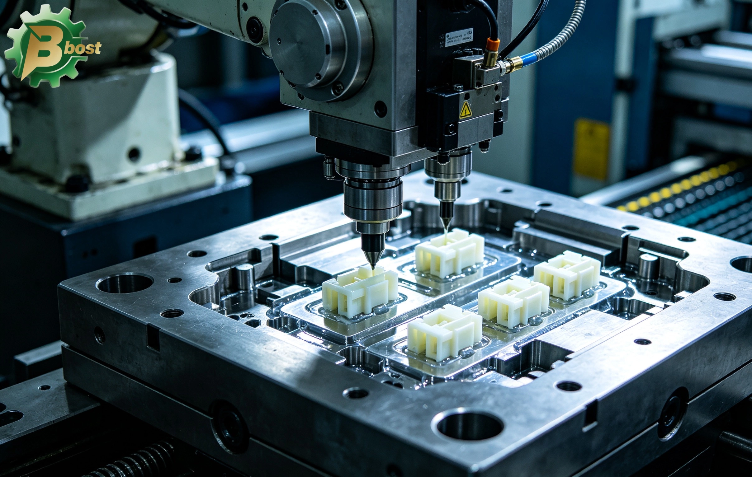
The location and type of gate (such as sub-gate, pin-point gate, or direct gate) directly determine the filling trajectory of the plastic melt. Improper design leads to obvious weld lines or air traps on the part's surface. We utilize Moldflow analysis software to simulate the entire injection process before cutting steel, optimizing gate locations in advance to eliminate potential defects.
3.2 Dynamic Thermal Balance of Mold Cooling Systems
Cooling time accounts for over 60% of the entire injection cycle. Uneven cooling causes different sections of the part to shrink inconsistently, creating internal stresses that induce warpage. By implementing conformal cooling channels, we ensure that the temperature variation across the mold surface is kept to an absolute minimum, dramatically boosting the dimensional stability of custom parts.
3.3 Flexible Tuning of Precision Injection Parameters
In actual production, injection pressure, holding pressure, speed, and melt temperature must undergo rigorous Scientific Injection Molding (SIM) testing. We execute T1 to T3 trials and provide comprehensive tryout reports alongside First Article Inspection (FAI) / CPK data, ensuring that mass-produced parts seamlessly align with your original drawings.
4. Quality Control: Digital Measurement Ensures Consistency
We completely understand that B2B overseas clients fear nothing more than samples that look perfect but mass production batches that fall short. To rigidly execute drawing standards, a full-process quality control chain must be established:
-
Incoming Quality Control (IQC): Testing the Melt Flow Index (MFI) and moisture content of plastic pellets for every batch to prevent dimensional fluctuations caused by raw material instability.
-
In-Process Quality Control (IPQC): On the precision injection production line, operators and QC inspectors regularly sample critical dimensions, using high-precision 2D optical measuring machines and Coordinate Measuring Machines (CMM) for digital comparison.
-
Outgoing Quality Control (OQC): Providing an exhaustive full-dimension report, ensuring that every single one of the custom plastic parts according to drawing delivered to your hands is impeccable.
Real Industry Case Sharing:
A European medical equipment client once sent us a drawing for an extremely complex air pump valve seat made of POM, requiring a critical mating tolerance of $\pm0.03\text{mm}$. Because POM features high shrinkage and isotropic tendencies, ordinary manufacturers struggle to control it. Our tooling team resolved this via 3D Moldflow analysis, changing the traditional single gate into a precision three-point symmetrical pin gate, and designed independent water temperature control systems. Ultimately, we successfully delivered custom parts that perfectly met the client's drawing tolerances at the T2 stage, achieving a mass production assembly pass rate of 99.8%.
5. Partner with GZ-Bost to Bring Your Drawings to Life Flawlessly
On the path of developing custom plastic parts, you don't just need a contract manufacturer; you need an engineering partner who understands your design language. GZ-Bost focuses on delivering top-tier injection molding solutions for you. Backed by a highly experienced engineering team, state-of-the-art high-precision processing machinery, and a stringent quality management system, we excel at transforming complex drawings into cost-effective, high-quality physical hardware.
If you have an active project requiring evaluation, or if you are looking for a premium injection molding supplier capable of efficiently delivering custom plastic parts according to drawing, please visit our official website right away: GZ-Bost Official Website to submit your 2D/3D drawings (STEP, IGS, or PDF formats). Our technical experts will provide you with a free DFM manufacturability evaluation and a highly competitive project quote within 24 hours.
Recommended for you
The Peak Art of Custom Manufacturing According to Drawings: Comprehensive Guide to Precision Solutions for Custom Parts According to Drawing
Ending Mechanical Wear and Resonance: The Comprehensive Guide to Precision Customization and Mass Production of a Custom Rubber Pad
The Ultimate Armor for Smart Hardware: Advanced Customization and Precision Injection Molding Guide for a Custom Plastic Box
The Ultimate Weapon to Tame Vibration and Noise: Deep Dive into the Custom Process and Mass Production Logic of a Custom Rubber Bushing
Product Categories
FAQ
FAQs
Can Bost customize modified plastics with special properties?
Yes! We offer modification services such as reinforcement, flame retardancy, conductivity, wear resistance, and UV resistance, for example:
• Adding carbon fiber to enhance stiffness
• Reducing the coefficient of friction through PTFE modification
• Customizing food-grade or medical-grade certified materials
What are the core advantages of Bost engineering plastics compared to ordinary plastics?
Bost engineering plastics feature ultra-high mechanical strength, high-temperature resistance (-50°C to 300°C), chemical corrosion resistance, and wear resistance. Compared to ordinary plastics, their service life is extended by 3 to 8 times, making them suitable for replacing metals in harsh environments.
What is the minimum order quantity (MOQ)? Do you support small-batch trial production?
The MOQ for standard products is ≥100kg. We support small-batch trial production (as low as 20kg) and provide mold testing reports and performance data feedback.
What is the delivery lead time? Do you offer global logistics?
Standard products: 5–15 working days; custom modifications: 2–4 weeks. We support global air/sea freight and provide export customs clearance documents (including REACH/UL certifications).
How do I select the appropriate engineering plastic grade for my product?
Selection should be based on parameters such as load conditions (e.g., pressure/friction), temperature range, medium contact (e.g., oil/acid), and regulatory requirements (e.g., FDA/RoHS). Our engineers can provide free material selection consulting and sample testing.
You may also like
Custom Plastic Knobs Precision Injection Molded
More Details →
Custom Plastic Knobs Precision Injection Molded
Custom Injection Molded Parts from Drawings
More Details →
Custom Injection Molded Parts from Drawings
Underwater Camera Shell Custom Plastic Molding
More Details →
Underwater Camera Shell Custom Plastic Molding
Leave a Message
Have any questions or concerns about our products? Please leave us a message here, and our team will get back to you promptly.

24 hours quotes delivered
Submit CAD files, get quote in 24 hours

No MOQ required
From prototyping to high-volume

±0.02 mm Precision
Advanced CNC with full inspections

1,000+ tons in stock
26 materials ready to ship
© 2026 BOST. All Rights Reserved.