




 Scan QR Code
Send My Request
From Blueprint to Component: Efficient Pathways to Turn Custom Parts According to Drawing into Reality
2026-06-10
Custom parts according to drawing require precision and efficiency—Bost outlines proven methods to streamline production from blueprint to finished component. Learn how to optimize custom plastic parts from drawings and CNC machined plastic parts to drawing for reliable, high-quality results.
- 1. The Initial Conversion Step: Decoding Critical Engineering Metrics Within the Drawing
- 1.1 Segregating Plastic Tolerances from Elastomeric Rubber Tolerances
- 1.2 Auditing GD&T (Geometric Dimensioning and Tolerancing)
- 2. Manufacturing Technology Alignment: Choosing the Optimal Path Based on Blueprint Requirements
- 3. The Four Foundational Engineering Milestones from Blueprint to Volume Production
- 3.1 Exhaustive Front-End DFM (Design for Manufacturability) Technical Alignment
- 3.2 Computational Fluid Simulation & High-Precision Mold Design
- 3.3 Precision Injection Molding and Closed-Loop Parametric Regulation
- 3.4 Rigorous Quality Assurance & Metrology Inspection
- 4. Why Partner with Guangzhou BOST for Your Drawing-Based Configurations?
- 5. Initiate Your "Blueprint to Component" Sourcing Project Today
In today’s globalized B2B manufacturing supply chain, a precisely engineered drawing (2D/3D CAD blueprint) serves as the primary universal language between overseas buyers and domestic production facilities. This communication channel is critical when dealing with custom components like a custom rubber plug or complex, irregularly shaped rubber and plastic parts. The primary mandate of procurement and engineering teams remains clear: how to guarantee that a production partner can reliably deliver custom parts according to drawing while maintaining tight dimensional tolerances across volume production runs.
Yet, during international sourcing campaigns, overseas engineers and sourcing managers frequently bump into systemic obstacles. For instance, a print might declare an exceptionally tight tolerance specification (such as $\pm0.02\text{mm}$), but the initial evaluation samples shipped from a traditional rubber shop continuously return oversized or undersized. Alternatively, a lack of proactive front-end engineering conversion often introduces volume production defects like heavy parting-line flash, internal air entrapment, or severe shrinkage.
As a premium manufacturing supplier specialized in international, high-specification contract production, Guangzhou BOST leverages its extensive tenure in precision injection molding and fluid-sealing component formulation to provide an expert analysis on seamlessly transforming design blueprints into premium industrial components.
1. The Initial Conversion Step: Decoding Critical Engineering Metrics Within the Drawing
The moment a design file for a custom rubber plug or specialized component arrives at our engineering hub, our technical team skips the guesswork. Instead, we perform a comprehensive engineering translation and manufacturing feasibility assessment on all critical specifications detailed within the print.
1.1 Segregating Plastic Tolerances from Elastomeric Rubber Tolerances
This technical nuance represents one of the most widespread pitfalls encountered by cross-disciplinary hardware designers. Many R&D generalists accustomed to the ultra-tight, predictable tolerances of rigid thermoplastics apply those identical parameters when drafting a rubber-based custom rubber plug.
-
Rigid Thermoplastics: Controlled via mature (mold design) and precise execution of the injection molding process, dimensions can comfortably hold tolerances tighter than $\pm0.05\text{mm}$.
-
Elastomeric Rubber Compounds: Rubber behaves as a high-molecular-weight elastomer, displaying substantial thermal expansion, contraction, and post-molding shrinkage traits. Consequently, elastomeric components must strictly refer to international standards such as ISO 3302-1 Class M1 (Precision Grade) or Class M2 (Standard Grade). Enforcing extreme thermoplastic tolerance zones on flexible rubber geometries drives tool-making expenditures up and spikes scrap rates during production.
1.2 Auditing GD&T (Geometric Dimensioning and Tolerancing)
For sophisticated campaigns involving custom parts according to drawing, baseline length, width, and height metrics are only part of the equation. Geometric attributes like coaxiality, roundness, and flatness dictate field assembly success. For example, a waterproof rubber bumper engineered for an electric vehicle battery pack enclosure might exhibit out-of-spec roundness along its primary sealing lip. Even if its mean diameter passes inspection, the variation can lead to localized compression failures and fluid ingress.
2. Manufacturing Technology Alignment: Choosing the Optimal Path Based on Blueprint Requirements
To clarify how to pair blueprint demands with the most efficient, cost-effective processing method, we have compiled a structural comparison of the two primary processing methodologies utilized across the industrial sector:
| Key Blueprint Metric Requirements | Recommended: Precision Injection Molding Process | Alternative: Traditional Vacuum Compression Molding |
|---|---|---|
| Geometric Complexity Profile | Extremely Advanced. Seamlessly supports internal blind bores, fine threads, and radial undercuts. | Low to Moderate. Deeply complex profiles present severe ejection risks and short-shot vulnerabilities. |
| Insert Molding Requirements | Excellent. Optimal for prints requiring rubber or plastic chemically or mechanically bonded to metal armatures. | Fair. Metal armatures risk shifting within open cavities during manual placement, disrupting position accuracy. |
| Tolerance Containment Limits | Maintains high-precision tolerance bandwidths with minimal part-to-part variation. | Features wider tolerance envelopes, heavily influenced by manual pre-form weight variances. |
| Surface Topography & Flash | Minimizes parting-line definitions; yields mirror-polish aesthetics based on tool standards. | Produces heavy flash zones; frequently necessitates labor-intensive manual deflashing processes. |
| Optimal Economic Run Sizes (MOQ) | Suited for medium-to-large high-volume campaigns or projects with non-negotiable performance metrics. | Best reserved for early prototyping validation or low-volume runs under a few hundred units. |
As demonstrated by this operational breakdown, if your technical drawing presents rigorous demands regarding complex configurations, tight tolerance boundaries, and clean aesthetic finishes, choosing a precision injection molding setup offers a reliable, repeatable, and cost-effective approach over the long run.
3. The Four Foundational Engineering Milestones from Blueprint to Volume Production
To implement a reliable production cycle for manufacturing custom parts according to drawing, an operation must execute four interconnected engineering control phases:
3.1 Exhaustive Front-End DFM (Design for Manufacturability) Technical Alignment
Prior to cutting tool steel, our application engineers engage in direct technical consultation with your R&D departments. We analyze the print for manufacturing red flags—such as severe cross-sectional wall deviations, inadequate draft angles, or sharp internal radiuses—and offer optimization advice. For instance, modifying a subtle chamfer on the rear skirt of a custom rubber plug allows the elastomeric material to flow more freely during the injection molding process, eliminating cosmetic air voids.
3.2 Computational Fluid Simulation & High-Precision Mold Design
Utilizing advanced Moldflow simulation systems, we conduct virtual molding trials on your CAD files. This software maps out the velocity and thermal trajectories of the molten compound under intense pressure, revealing weld lines, sink markers, and high-risk flash areas before manufacturing begins. This data guides our automated (mold design), locking in the required geometric dimensions right at the source.
Field Case Study: A European industrial automation enterprise approached us to contract a complex custom rubber plug featuring specialized raised retaining ribs. After checking their 3D models, we deployed micron-level wire EDM and precision RAM CNC machining to build the tooling. The volume production parts demonstrated an absolute deviation from the blueprint of under $0.03\text{mm}$, solving a chronic field loose-fit issue the client faced with their prior vendor.
3.3 Precision Injection Molding and Closed-Loop Parametric Regulation
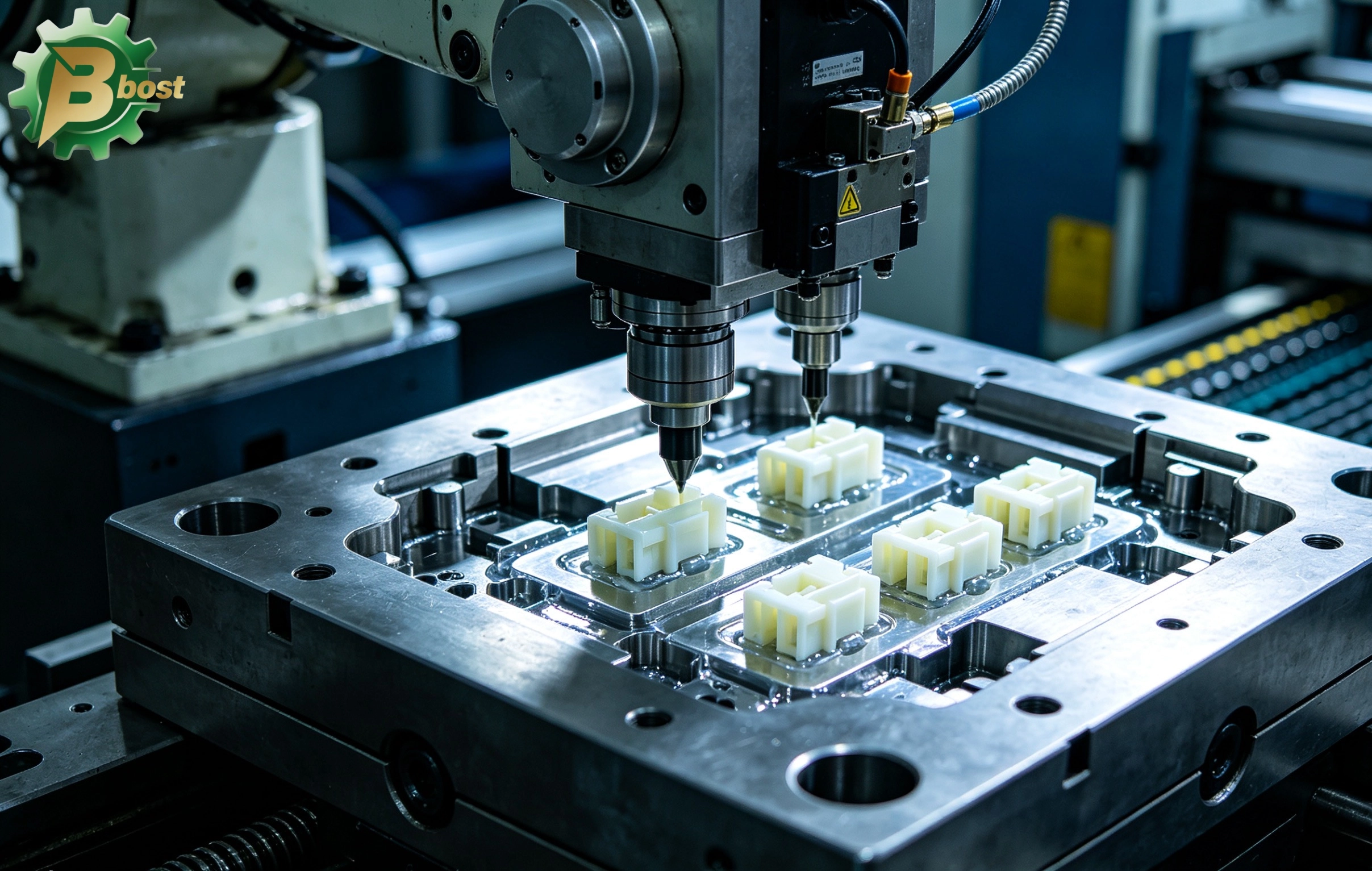
Out on the production floor, manufacturing runs on automated molding machinery. The entire cross-linking, vulcanization, and cooling curve of the polymer or rubber is tracked in real-time by a centralized computer monitoring array. By locking down injection velocities, pack-and-hold pressures, and thermal baselines, we ensure that every single component pulled from the cavity exhibits identical physical and dimensional attributes.
3.4 Rigorous Quality Assurance & Metrology Inspection
Every alphanumeric character on your drawing represents a non-negotiable standard for our quality assurance team. Guangzhou BOST maintains a metrology lab equipped with automated vision projection systems, coordinate measuring machines (CMM), and calibrated durometer testing rigs. We execute systematic First Article Inspections (FAI) and Outgoing Quality Control (OQC) sequences, shipping every consignment alongside detailed Dimensional Inspection Reports and traceable Material Certifications.
4. Why Partner with Guangzhou BOST for Your Drawing-Based Configurations?
Translating a complex engineering print into high-quality physical hardware requires more than just industrial machinery; it demands field-tested manufacturing experience and a disciplined engineering culture.
Guangzhou BOST brings over a decade of experience serving global B2B industrial accounts and managing complex international contracts. We offer the following core competencies:
-
Comprehensive Print Literacy: Our engineering team reads, interprets, and converts international drawing standards (including ISO, ANSI, DIN, and JIS) across mainstream CAD formats such as
.STEP,.IGS, and.DWG. -
Extensive Material Matrix: Whether your drawing mandates standard EPDM, Nitrile (NBR), or high-performance Fluorocarbon (Viton), Liquid Silicone Rubber (LSR), or advanced engineering thermoplastics (PA66, PEEK, PC), we provide exact compound compounding and processing services.
-
Seamless Engineering Communication: Our technical advisors are fluent in international B2B technical communication, allowing them to engage directly with overseas engineering teams and eliminate interpretation errors caused by language barriers.
5. Initiate Your "Blueprint to Component" Sourcing Project Today
In the procurement of non-standard industrial components, timeline delays translate directly to lost revenue, and dimensional precision dictates field viability. Do not let your product configurations remain confined to a digital file due to a lack of premium manufacturing support.
If you are currently managing a campaign requiring custom parts according to drawing or a specialized custom rubber plug slated for custom tooling and mass production, we invite you to visit our official engineering portal: [https://www.gz-bost.com](https://www.gz-bost.com](https://www.gz-bost.com).
Through our integrated quote management system, you can securely upload your 2D/3D engineering prints along with your material sheets. The senior technical application team at Guangzhou BOST will deliver a comprehensive DFM feasibility report and a competitive B2B commercial quote within 24 hours. Let our (precision injection molding) infrastructure turn your technical concepts into high-performance realities!
Recommended for you
The Peak Art of Custom Manufacturing According to Drawings: Comprehensive Guide to Precision Solutions for Custom Parts According to Drawing
Ending Mechanical Wear and Resonance: The Comprehensive Guide to Precision Customization and Mass Production of a Custom Rubber Pad
The Ultimate Armor for Smart Hardware: Advanced Customization and Precision Injection Molding Guide for a Custom Plastic Box
The Ultimate Weapon to Tame Vibration and Noise: Deep Dive into the Custom Process and Mass Production Logic of a Custom Rubber Bushing
Product Categories
FAQ
FAQs
Can Best customize modified plastics with special properties?
Yes! We offer modification services such as reinforcement, flame retardancy, conductivity, wear resistance, and UV resistance, for example:
• Adding carbon fiber to enhance stiffness
• Reducing the coefficient of friction through PTFE modification
• Customizing food-grade or medical-grade certified materials
How do I select the appropriate engineering plastic grade for my product?
Selection should be based on parameters such as load conditions (e.g., pressure/friction), temperature range, medium contact (e.g., oil/acid), and regulatory requirements (e.g., FDA/RoHS). Our engineers can provide free material selection consulting and sample testing.
What is the delivery lead time? Do you offer global logistics?
Standard products: 5–15 working days; custom modifications: 2–4 weeks. We support global air/sea freight and provide export customs clearance documents (including REACH/UL certifications).
What is the minimum order quantity (MOQ)? Do you support small-batch trial production?
The MOQ for standard products is ≥100kg. We support small-batch trial production (as low as 20kg) and provide mold testing reports and performance data feedback.
What are the core advantages of Best engineering plastics compared to ordinary plastics?
Best engineering plastics feature ultra-high mechanical strength, high-temperature resistance (-50°C to 300°C), chemical corrosion resistance, and wear resistance. Compared to ordinary plastics, their service life is extended by 3 to 8 times, making them suitable for replacing metals in harsh environments.
You may also like
Custom Plastic Knobs Precision Injection Molded
More Details →
Custom Plastic Knobs Precision Injection Molded
Custom Injection Molded Parts from Drawings
More Details →
Custom Injection Molded Parts from Drawings
Underwater Camera Shell Custom Plastic Molding
More Details →
Underwater Camera Shell Custom Plastic Molding
Leave a Message
Have any questions or concerns about our products? Please leave us a message here, and our team will get back to you promptly.

24 hours quotes delivered
Submit CAD files, get quote in 24 hours

No MOQ required
From prototyping to high-volume

±0.02 mm Precision
Advanced CNC with full inspections

1,000+ tons in stock
26 materials ready to ship
© 2026 BOST. All Rights Reserved.